PCB Design
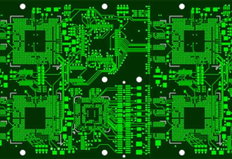
- The Electronic design called a schematic or circuit diagram. It is constructed in CAD format. Schematic diagram are constructed according to a number of standard and rules, but the primary function is to explain the circuit design in an easily digestible form.
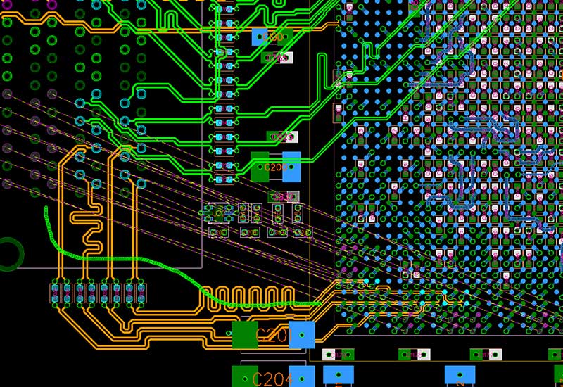
- We Specializes in high-performance PCB physical design (layout) while utilizing high-end software programs complemented by leading edge Hardware.
- Single ended and differential controlled impedance design.
- Design for manufacturing/test/assembly.
- Placement of critical components as per customer spec.
PCB Fabrication
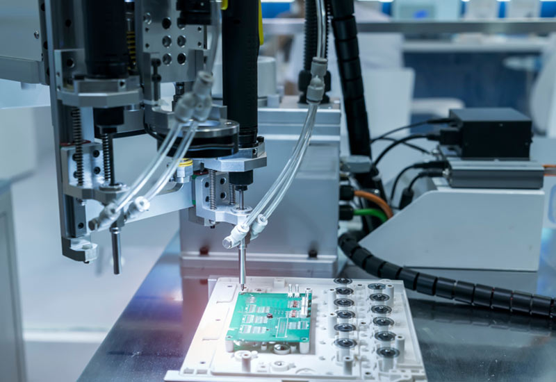
- A PCB is used to connect electronic components electrically. This is done by making conductive pathways for circuit connections by etching tracks from copper sheet laminated onto a non-conductive substrate.
- A PCB consists of a conducting layer that is made up of thin copper foil. The insulating layer dielectric is laminated together with epoxy resin prepreg. The most commonly used PCB type is the FR-4. Boards may be single-sided or double-sided. Double-sided PCB can be used to connect electronic components on both sides through through-hole plating. This is done by copper plating the walls of each hole so as to connect the conductive layers of the PCB.
PCB Reverse Engineering
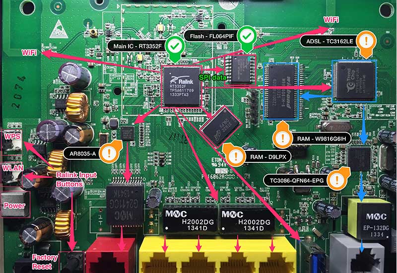
- PCB Layout design (Single & double Layers).
- Component Library creation as per IPC Standard.
- Design for surface mount, through-hole & mixed technology with QFN, BGA, PGA & fine pitch component.
- Design as per EMI/EMC requirement.
- Design for assembly.
PCB Stencil
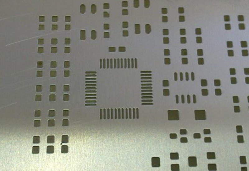
- The primary function of using SMT stencil is to facilitate the placing of the component onto aboard after a cost of solder paste is applied on it.
- Framed stencil advantage DFM study for all jobs and can combine command F2 polishing F3 Nano coating & also aperture size accuracy of +5um and positioning accuracy +10um.
PCB Cad-Cam
- Checking the specifications, any drawings & Gerber data given by the customer.
- Making array as per customer drawing to reach customer assembling requirement.
- Preparing required documentation from received inputs for production, depending upon customer requirements.
- CAD Drafting Professional with board understanding of Design and Construction process with Exceptional creativity, Problem-solving and interpersonal skill.
- Quote data preparation
- Design Rule Check (DRC)
- DFM Optimization
- Array Creation
- Penalization
- AOI, Drill, ET, Rout program for production etc.
